gpu_accelerated_2d_physical_model
GPU-Accelerated Physical Model For Real-time Drumhead Synthesis
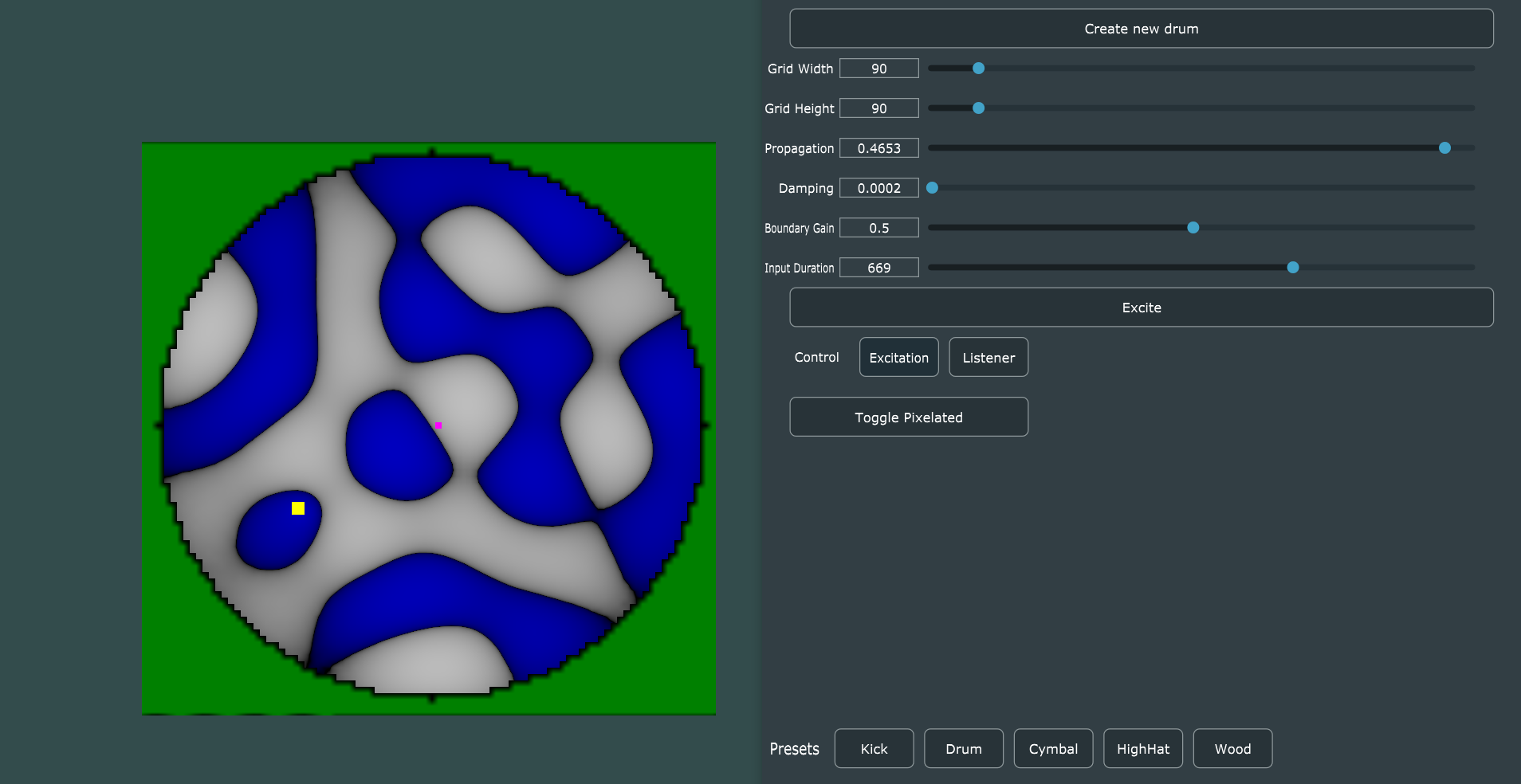
This post covers the highlights of the code base used to present the GPU-accelerated drumhead physical model program. This application was demonstrated at the Audio Developers Conference (ADC 2019) and the conference of New Instruments for Musical Expression (NIME 2020). The application presents a model of a 2D drumhead physical model based on direct numerical methods from mathematical simulations. Specifically, the model uses finite differencing methods based within the time-domain. These methods are known as finite-difference time-domain(FDTD) simulations. Therefore, the GPU-accelerated drumhead physical model will be referred to as such in the rest of the post.

FDTD synthesizer
The focus of this post is on the whole system and its interacting components. Meaning, we cover how the FDTD synthesizer is included in a JUCE playback & GUI application, along with how a physical device like the Sensel Morph can be added as a way to interact with the synthesizer. This post will not cover the detailed inner workings of the FDTD synthesizer. Instead, the FDTD synthesizer will be covered in another dedicated post. To cover it briefly, the FDTD synthesizer is based on a 2D cartesian grid. The simple 2D wave equation is applied to the grid in a discrete, finite-difference scheme. The equation exposes three coefficients as potential parameters: Propagation, damping and boundary gain. The propagation coefficient determines the speed of wave propagation through the medium, the damping coefficient determines the amount of energy absorbed into the medium as it transfers through it and finally, the boundary gain is the amount the wave is reflected back into the model at the edges. The implementation of the FDTD synthesizer in this application uses OpenGL, a graphics rendering API to process the FDTD simulation in real-time. We have developed other implementations, which can be found here.
GPU Acceleration
The novelty to this demonstration is that it can achieve a real-time(Or at least near real-time) performance by optimizing in C++ and offloading the processing to the Graphics Processing Unit(GPU). GPUs are common place in almost all computer systems now. In recent years, they have become more than just an accelerator for graphics specifically, but also for general computation. GPUs process in a massively parallel way that is best suited when there is a collection of similar data that requires the same set of instructions to be applied to them. A most simplistic example, think of a large array where every number needs to be doubled. Instead of a single CPU processor visiting each and multiplying by two, using a GPU with possibly a few hundred streaming processors that execute in parallel, multiplying by two can be applied to hundreds of the elements at once. There is much more to cover when considering the GPU architecture, but this will be covered another time.
OpenGL_FDTD Interface
To use the FDTD synthesizer, you only need to understand how to use a handful of simple public functions in the OpenGL_FDTD class.
OpenGL_FDTD(OpenGL_FDTD_Arguments args);
bool fillBuffer(unsigned long frames, void* inbuf, void* outbuf);
The “fillBuffer()” function should follow a familiar format to audio developers. Once the FDTD synthesizer has been initialized, it can be called to fill a buffer with new audio samples. By passing the number of samples to compute in the first argument, a buffer of input samples to ‘excite’ the model as the second and an output buffer where the generated samples will be written to. The initialization is a more verbose setup than might be expected. A single ‘OpenGL_FDTD_Arguments’ struct can be passed, which contains a collection of configuration information. See the struct below to understand what needs to be explicitly set.
struct OpenGL_FDTD_Arguments
{
    bool isDebug;                        //Sets if debug information is reported to output.
    bool isBenchmark;                    //Sets if benchmarking performance measurements are recorded.
    bool isVisualize;                    //Sets if the FDTD model is visualized in an OpenGL context.
    bool isLinearPixelInterpolation;    //Sets if the pixels in the OpenGL viualization are linearly interpolated, or just true value calculated at the position.
    FDTD_Shape shape;                    //Sets the shape of the boundary for the default boundary point.
    uint32_t modelWidth;                //Sets the size of the model in x dimension.
    uint32_t modelHeight;                //Sets the size of the model in y dimension.
    uint32_t bufferSize;                //Sets the buffersize, how many samples to generate per call to "fillBuffer(...)".
    uint32_t listenerPosition[2];        //Sets the location in the 2D model of the listener positions (Where in the model the audio samples are recorded from)
    uint32_t excitationPosition[2];        //Sets the location in the 2D model of the excitaiton position. (Where samples are input into the model)
    float propagationFactor;            //Sets the propgation coeffcient, determine wave speed.
    float dampingCoefficient;            //Sets damping coefficient, determines wave absorbtion.
    float boundaryGain;                    //Sets degree which waves are reflected on boundaries.
    std::string fboVsSource;            //Identifies paths to the FDTD processing vertex and fragment shaders.
    std::string fboFsSource;
    std::string renderVsSource;            //Identifies paths to the FDTD rendering vertex and fragment shaders.
    std::string renderFsSource;
};
In the current implementation, making changes to the FDTD synthesizer configuration requires recreating the object by calling its constructor. In the future, many of these parameters should be modifiable and take effect without the model needing to be recreated.
Audio Playback and GUI Environment
Originally, Portaudio was used in development for the real-time playback functionality. However, there seemed to be problems using portaudio for this application, specifically for supporting the real-time processing of the FDTD model. Instead, this application has been developed within the JUCE environment. JUCE provides real-time playback functionality in the form of defining virtual callback functions which are called internally to obtain audio samples to play through an available audio device. The use of the FDTD synthesizer class in a JUCE application demonstrates the easy integration of the FDTD synthesizer into new projects.
Initializing the FDTD Model
The FDTD model is initialized when the parameters in the GUI are changed or one of the buttons to recreate a preset configuration is pressed. Therefore, the FDTD model is initialized on GUI callback events.
void MainComponent::buttonClicked(Button* btn);
void MainComponent::sliderDragEnded(Slider* sld);
These two JUCE virtual functions are defined to handle button clicks and slider changes. When a parameter is changed for the model, the parameter that is changed is checked and the FDTD synthesizer constructor is called to initialize the new configuration. An example of the propagation factor slider change is shown below.
if (sld == &sldPropagation)                                    //If slider changed is propagation factor.
{
    glArgs.propagationFactor = sldPropagation.getValue();    //Get the new value for propagation factor.
    if (glFDTDAlive_)                                        //If the FDTD model already exits, delete it.
    {
        glFDTD->closeWindow();
        delete(glFDTD);
    }
    glFDTD = new OpenGL_FDTD(glArgs);                        //Create the new FDTD model with new propagation factor.

    reinitSignal.set(0);
    glFDTDAlive_ = true;                                    //Indicates that the FDTD model now exists in the program.
}
Audio Callback Function
JUCE provides the following virtual function to be defined for real-time audio playback.
void MainComponent::getNextAudioBlock(const AudioSourceChannelInfo& outputBuffer)
Inside this function, the programmer is expected to obtain or generate audio samples which must then be added to the buffer. This buffer will then be played through the chosen audio device by JUCE. This is a callback function that is called at a rate required by JUCE to sustain the constant audio rate set. In this application, the audio samples will be generated from the FDTD model executing on the GPU.
float* inputExcitation = new float[outputBuffer.numSamples];
for (int j = 0; j != outputBuffer.numSamples; ++j)
{
    inputExcitation[j] = sineExciter_.getNextSample();
    if (wavetableExciter_.isExcitation())
        inputExcitation[j] = wavetableExciter_.getNextSample();
    else
        inputExcitation[j] = 0;
    //inputExcitation[j] = senselPressure.get();
}
Every time a buffer of audio is to be generated, an equally sized buffer of input audio samples needs to be collected in a buffer. This is because the FDTD model should have an input sample inserted into the model as an “excitation” for every time-step processed. In the current implementation, a wavetable is used as input into the model at a position determined by the Sensel Morph contact. In the future, the input should use pressure from the contact as input to add velocity to excitation.
float* samples = new float[outputBuffer.numSamples];
glFDTD->setBufferSize(outputBuffer.numSamples);
glFDTD->fillBuffer(outputBuffer.numSamples, inputExcitation, samples);
To generate the samples needed from the FDTD model, the “fillBuffer()” function is called. Passing it the number of samples to generate, a buffer of input audio samples that will “excite” the model and the output buffer which the generated samples will be written to.
float* leftBuffer = outputBuffer.buffer->getWritePointer(0, outputBuffer.startSample);        //Get pointers to the left and right buffers JUCE plays back in real-time.
float* rightBuffer = outputBuffer.buffer->getWritePointer(1, outputBuffer.startSample);
memcpy((void*)leftBuffer, (void*)samples, outputBuffer.numSamples*sizeof(float));            //Copy generated samples into left and right JUCE buffers.
memcpy((void*)rightBuffer, (void*)samples, outputBuffer.numSamples * sizeof(float));
Once the samples buffer is filled with new, synthesized values from the FDTD model, the buffer’s contents are copied into the left and right JUCE buffers. The samples in these buffers will now be played back through the chosen audio device! Before copying the samples, there is the opportunity to apply further processing to the samples.
For more information and examples on JUCE’s audio functionality, check here.
Sensel Morph Interface
Sensel is a company that offers pressure grid touch sensors. Here, a Sensel Morph is used as a way of exciting the FDTD synthesizer, acting as a drumhead which the performer can touch or strike. The Sensel provides the points of contact and the pressure at each point of contact. Currently, the implementation uses the coordinates of the points of contact on the Sensel to set the position where excitation samples will be input into the FDTD model.
Initializing the Sensel Morph
The Sensel Morph is initialized once inside JUCE’s prepareToPlay virtual function.
void MainComponent::prepareToPlay(int samplesPerBlockExpected, double sampleRate)
{
    //Get connected Sensel Device//
    senselGetDeviceList(&list);
    if (list.num_devices == 0)
        senselWarning.setVisible(true);
    else
        senselWarning.setVisible(false);

    //Open a Sensel device by id in the SenselDeviceList and get info//
    senselOpenDeviceByID(&handle, list.devices[0].idx);
    senselGetSensorInfo(handle, &sensor_info);

    //Set and allocate the frame content//
    senselSetFrameContent(handle, FRAME_CONTENT_CONTACTS_MASK);
    senselAllocateFrameData(handle, &frame);

    //Configure Sensel scan detail, framerate and contact minimum force to detect//
    senselSetScanDetail(handle, SCAN_DETAIL_LOW);
    senselSetMaxFrameRate(handle, 500);
    senselSetContactsMinForce(handle, 10);

    //Start scanning the Sensel device for changes//
    senselStartScanning(handle);

    //Start the JUCE hiResTimerCallback timer - This will be called once every millisecond to poll Sensel for contacts//
    startTimer(1);
}
Collecting contact and pressure
In this application, the contact and pressure information is collected from the sensel by polling it for available information on a timer. JUCE provides a high-resolution timer as shown below.
void MainComponent::hiResTimerCallback()
This timer is set to be called once a millisecond. This results in the Sensel Morph being polled for available data once a millisecond. This time interval could be tuned for better performance, but in the current implementation was satisfactory.
Synchronization
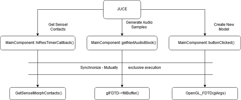
The application runs multiple-threads to achieve real-time performance. This involves a consistent simulation of the FDTD model executing on the GPU. To keep running, this requires careful management by the CPU. Along with this, the Sensel Morph is polled for new contact and the GUI interface has event callbacks when parameters are configured. When the FDTD synthesizer parameters are modified and must be recreated, the current simulation running on the GPU must finish processing. For stability, these two regions of code must, therefore, be mutually exclusive. In this implementation, this is achieved using mutex’s
void MainComponent::getNextAudioBlock(const AudioSourceChannelInfo& outputBuffer)
{
	mutexFDTD.lock();

	//FDTD synthesizer generates a buffer of samples...

	mutexFDTD.unlock();
}

void MainComponent::buttonClicked(Button* btn)
{
    if (btn == &btnCreateDrum)
    {
		mutexFDTD.lock();

		//Recreate FDTD synthesizer...

		mutexFDTD.unlock();
    }
}

Conclusion
This project aimed to demonstrate if GPU processing was a viable option for digital audio synthesis with real-time requirements. In this scenario, a FDTD synthesizer was processed on the GPU and appeared to meet acceptable real-time performance when interacting through a Sensel Morph pressure sensor. The dimensions/size of the physical models represented where only achievable on the modest laptop system by utilizing the massively parallel processing available from the GPU. In digital audio processing, there seems to be some reluctance to pursue GPU acceleration because of the communication overhead involved when using the GPU. With the correct techniques to reduce communication overhead and only processing suitable tasks on the GPU, there is huge potential for computing digital audio on GPUs.
You can find the source code for the current implementation here
Demonstration video download: PhysicalModelGPUDemonstration